The ends of connections are placed with the help of anchors. An anchor is a fixed or calculated location, usually associated with a graphical representation. The user must provide the source and target anchor, typically by dragging from and dropping onto the graphical representation of the anchors. The connection points can then be calculated automatically.
Currently the following different types of connection anchors are supported:
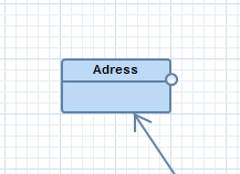
They can be created calling IPeCreateService.createChopboxAnchor. A chop box anchor is located virtually in the center of the parent. However, the connection line does not end at the center of the parent but already at the intersection-point with the parent boundaries. This means especially, that the intersection-point is re-calculated not only when the parents size or location changes, but also when the direction of the connection changes. Chop box anchors are the only anchors which do not need a graphics algorithm.
Figure: Chop box anchor (always pointing to the center)
They can be created calling IPeCreateService.createBoxRelativeAnchor. A box relative anchor is located relative to the size and location of the parent. The x/y-coordinates are defined as percentage values between 0.0 and 1.0. This allows for example to locate an anchor always at the middle-right border of the parent (x=1.0, y=0.5). The location of the anchor is re-calculated whenever the parents size or location changes.
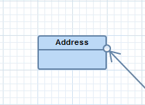
Figure: Box relative anchor (on middle-right border outside of shape)
They can be created calling IPeCreateService.createFixPointAnchor. A fix point anchor is located at fixed x/y-coordinates (relative to the parent).
Every connection has two connection anchors which provide the points where the connection starts/ends. Additionally the connection can have multiple bend-points in between. An anchor has two points: the “reference-point” is the logical end-point of the connection and the “location” is the visible end-point of the connection.
The following sketch explains those points for a chop box anchor.
Figure: Points of a chop box anchor
The reference-point (R) of the chop box anchor is the middle of the figure, because this is the point where the connection logically ends. The reference-point changes if the figure changes, but it does not change depending on the connection.
We define the point (O) as the other point where the connection logically ends. If the connection has bend-points, then (O) is the bend-point (B) next to the anchor, otherwise (O) is the reference-point (R) of the other connection anchor. This means, that logically the connection is a line from (R) to (O).
But a line drawn from (R) to (O) would overlap the figure. To avoid this overlap the location (L) of an anchor is calculated from (R) and (O) as the visible end-point of the connection. In case of the chop box anchor (L) is the intersection between the line (R - O) and the border of the figure.
The same algorithm is applied for all other anchor types, although often the calculation is much simpler. For example in a fix point anchor the reference-point (R) is the point the anchor was initialized with and the location (L) is identical to (R).
Note: All anchors have a graphical representation and connections are starting and ending virtually in the center of the graphical representation. But how can it be achieved that connections are starting precisely from the border of this graphical representation? For this purpose define a teh anchor location there and use setUseAnchorLocationAsConnectionEndpoint. At the end of this chapter is an example for this use case.
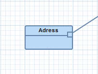
Figure: Box relative anchor with graphical representation inside border of shape
If the user shall be able to create connections directly via drag & drop from an anchor without the connection-tool, this can be implemented by so called drag & drop features. This does not work for chop box anchors, because they have no visible anchor which can be dragged.
To offer drag & drop functionality from anchors we have to overwrite the getDragAndDropFeatures method of the feature provider.
If this method returns exactly one feature it will be executed directly on drop (if applicable). If you provide more than one feature the user will be presented a popup menu on drop showing all applicable features (applicable means canExecute returns true). The user can select the desired feature which will be executed then.
In this example we first add a box relative anchor on the middle-right border of a EClass. Then we support drag & drop from that anchor to another EClass, which will create a new connection.
First the box relative anchors have to be created at the end of the add-method of the TutorialAddEClassFeature, as explained in the following code snippet. Note, that the previously created chop box anchor (see create connection feature) remains, so that the EClass has then two anchors:
public PictogramElement add(IAddContext
context) {
// ... EXISTING CODING ...
// add a chopbox anchor to the shape
peCreateService.createChopboxAnchor(containerShape);
// create an additional box relative anchor at middle-right
final BoxRelativeAnchor boxAnchor =
peCreateService.createBoxRelativeAnchor(containerShape);
boxAnchor.setRelativeWidth(1.0);
boxAnchor.setRelativeHeight(0.38); //use golden section
boxAnchor.setReferencedGraphicsAlgorithm(roundedRectangle);
// assign a rectangle graphics algorithm for the
box relative anchor
// note, that the
rectangle is inside the border of the rectangle shape
final Rectangle rectangle =
gaService.createPlainRectangle(boxAnchor);
rectangle.setForeground(manageColor(E_CLASS_FOREGROUND));
rectangle.setBackground(manageColor(E_CLASS_BACKGROUND));
rectangle.setLineWidth(2);
gaService.setLocationAndSize(rectangle, -12, -6, 12, 12);
// call the layout
feature
layoutPictogramElement(containerShape);
return containerShape;
}
Additionally the feature provider has to deliver the drag & drop features (overwrite the method getDragAndDropFeatures).
In this very simple implementation all create connection features are returned independent of the given context:
@Override
public IFeature[]
getDragAndDropFeatures(IPictogramElementContext context) {
// simply return all create connection features
return getCreateConnectionFeatures();
}
Note: A more sophisticated solution with an anchor on a EClass with an extended rendering area like the examples at the beginning is shown in chapter selection behavior.
Start the editor again and create two new EClasses (existing EClasses don’t work, because they have no anchor). Then drag the anchor at the middle-right border of the first EClass and drop it onto the second EClass. This will create a new connection between those two EClasses.
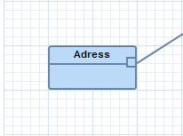
Figure: Box relative anchor with an anchor location as end-point
The above image shows a connection which has an end-point directly on the border of the rectangle on the right. The rectangle is the graphical representation of the box relative anchor. Using a location on the the right border of the anchor as end-point will be possible by invoking setUseAnchorLocationAsConnectionEndpoint on the anchor.
public PictogramElement add(IAddContext
context) {
// ... EXISTING CODING ...
// create an box relative anchor at middle-right
final BoxRelativeAnchor boxAnchor =
peCreateService.createBoxRelativeAnchor(containerShape);
boxAnchor.setRelativeWidth(1.0);
boxAnchor.setRelativeHeight(0.38); //use golden section
boxAnchor.setUseAnchorLocationAsConnectionEndpoint(true);
boxAnchor.setReferencedGraphicsAlgorithm(roundedRectangle);
// assign a rectangle graphics algorithm for the
box relative anchor
// note, that the
rectangle is inside the border of the rectangle shape
final Rectangle rectangle =
gaService.createPlainRectangle(boxAnchor);
ellipse.setForeground(manageColor(E_CLASS_FOREGROUND));
ellipse.setBackground(manageColor(E_CLASS_BACKGROUND));
ellipse.setLineWidth(2);
// anchor is located on the right border of the visible
rectangle
// and touches the border of
the invisible rectangle
gaService.setLocationAndSize(rectangle, -12, -6, 12, 12);
// call the layout feature
layoutPictogramElement(containerShape);
return containerShape;
}