
This part of the documentation deals with features provided by the integration to Papyrus.
For a better experience, you should activate the Papyrus Perspective before reading this documentation.
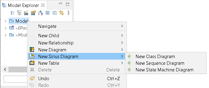
Once a UML model is created, go into the Model Explorer, select a UML element from which to start the document, then Right-Click-> New Class Diagram.
The corresponding sirius diagram is opened inside Papyrus.
Or from the View Explorer, click on the create view, select the root element and finally the view to create.
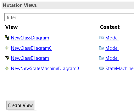
The created DSemanticDiagram are displayed in the ModelExplorer as children of the element . This customization is not loaded by default.
Open the Model Explorer view and use the customize model explorer to load the Sirius Diagram customization:

To have a global overview of sirius diagram. You can have a look at the sirius diagram documentation. See https://www.eclipse.org/sirius/doc/user/diagrams/Diagrams.html
While most part is similar to the former GMF diagram. There are some small differences between both.
Sirius Diagram provides a synchronization mechanism. The user can Synchronize/Unsynchronize each diagram using the contextual menu.
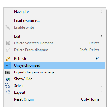
In addition, Sirius is able to display the status (Synchronized/Unsynchronized) of the diagram in its bottom right corner.
NB: At the startup, Papyrus activates these two Sirius preferences: - new diagram are unsynchronized - the diagram status is displayed for the new diagram
The Unsynchronized status:

The synchronized status:

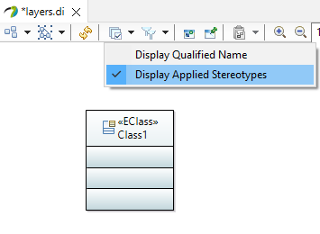
Layers can be defined to hide or show several mapping and/or several tools in the palette in a diagram. We also use this feature to show/hide applied stereotypes and qualified name in the labels of the elements displayed in the diagram.
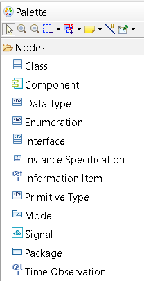
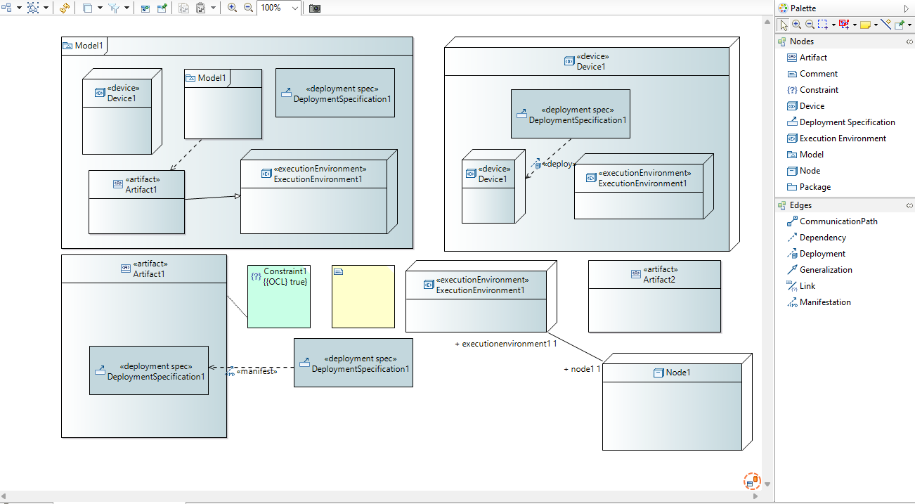
Palette tools is divided in two categories, one for the creation of element represented has nodes and the other for the creation of edge elements.
Drag and drop tools have been implemented to allow to create views for existing element that are not represented yet in the diagram.
Drag and drop inside diagram is also available, but depending of the kind of element that is drag and drop, the behavior can be different.
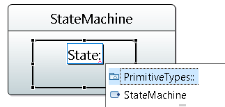
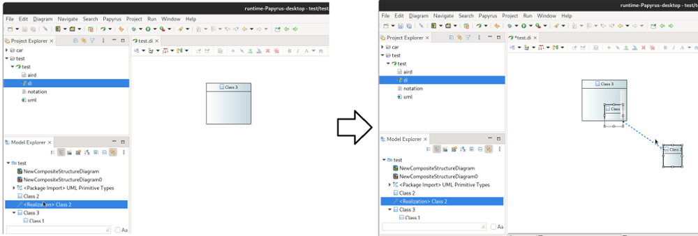
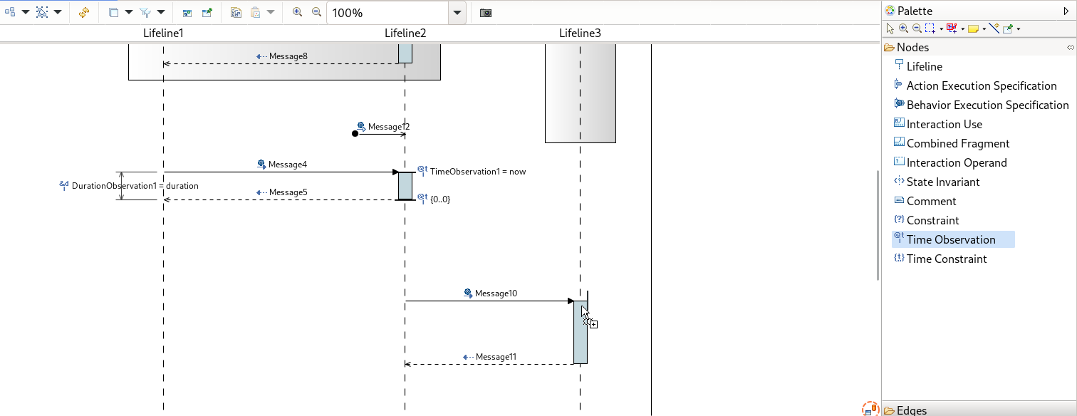
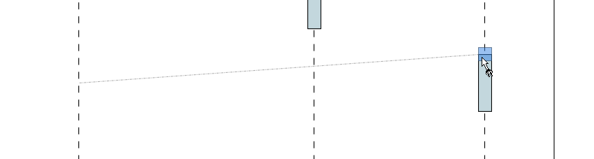
When the Drag and Drop of a Node or BorderNode is authorized on a NodeContainer or Node, the target appears highlighted. Otherwise, if Drag and Drop is not authorized for a Node or BorderNode, the target NodeContainer or Node is not highlighted. For BorderNodes, the phantom of the moved graphical element always appears on Drag and Drop compatible zones (i.e. the border of a NodeContainer or Node), but this does not mean that Drag and Drop is possible if the target element is not highlighted.
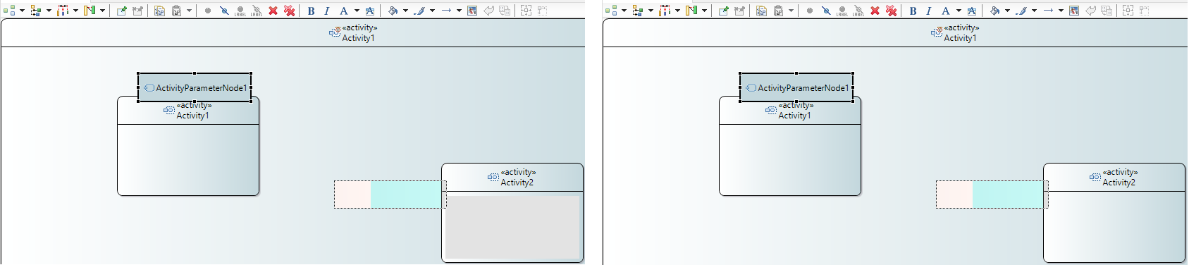
On the left image, Drag and Drop is allowed. On the right, Drag and Drop is not allowed.
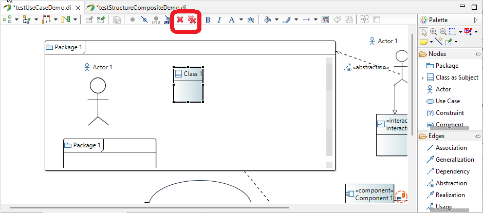
To delete element from diagram only, user selects first the element on diagram to remove and then he can click on "Delete from Diagram" button in the toolbar. This button is only available when diagram is unsynchronized. To delete element from model, user selects first the element to remove and then he can click on "Delete from Model" button in the toolbar. The element will be removed semantically and from diagram whatever activated synchronize mode.
Deletion of graphical element (only the view, not the semantic element) can be done using the shortcut (SHITF + DEL)
Deletion from the model can be done using a simple delete with DEL key.
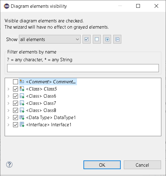
Using the shortcut CTRL + H, you can simply show or hide and element from the diagram.
When the user selects an element in a Sirius Diagram, this element is selected in the Papyrus ModelExplorer.
When the user selects an element in a Sirius Diagram, the property view of this element is displayed.
When the user selects an element in the ModelExplorer, if the open Diagram contains a graphical representation of this element, this one is selected.
Pinning an element makes it protected from any action which can modify the position of this element in the diagram, such as arrange all.
Xtext autocompletion is available when renaming an element using direct edition with F2 shortcut. When using Ctrl + Space key, the auto completion tool propose a list of label to use.
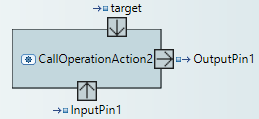
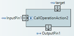
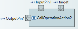
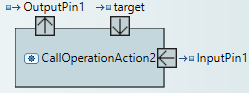
Rotative images can be applied to Bordered Nodes. These Bordered Nodes use an image whose orientation depends on the position of the Bordered Node regarding its parent Node or Container. For example, with the InputPin and OutputPin on the Activity diagram, the arrow image used in these Bordered Nodes rotates according to the North/South/East/West position of the Bordered Node.
Since Sirius 7.2.0, the popup bar is now displayed when the mouse is hover a diagram element. This popup displays available tools for this specific element.
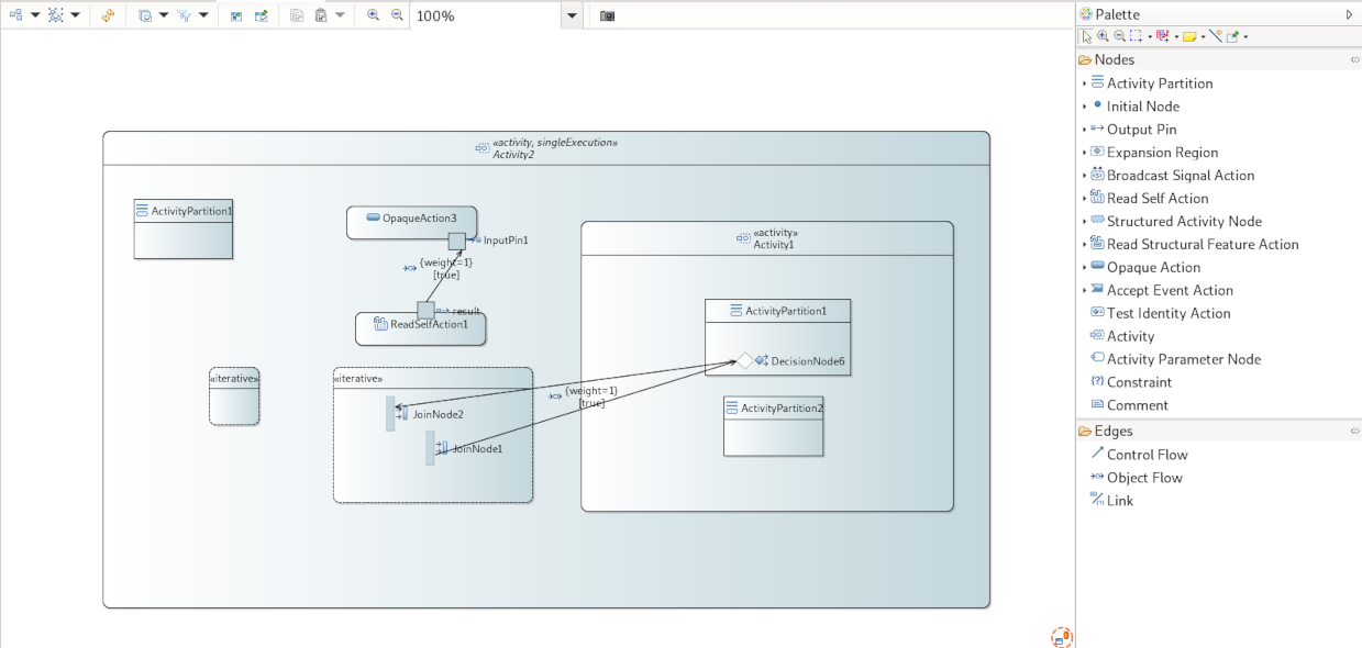
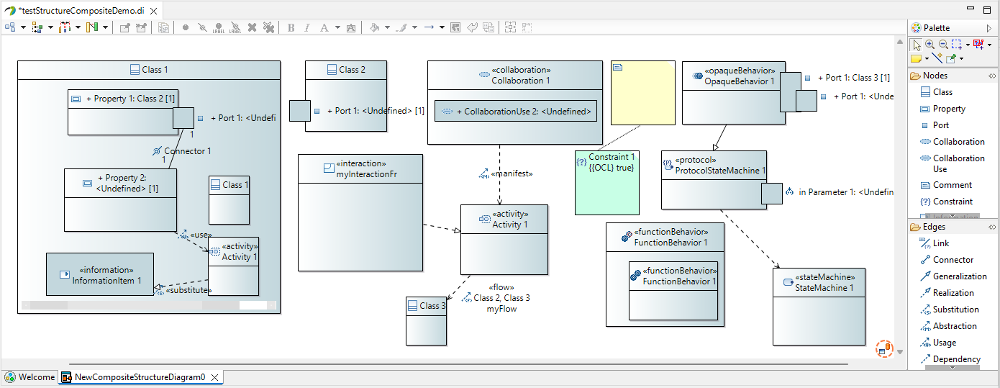
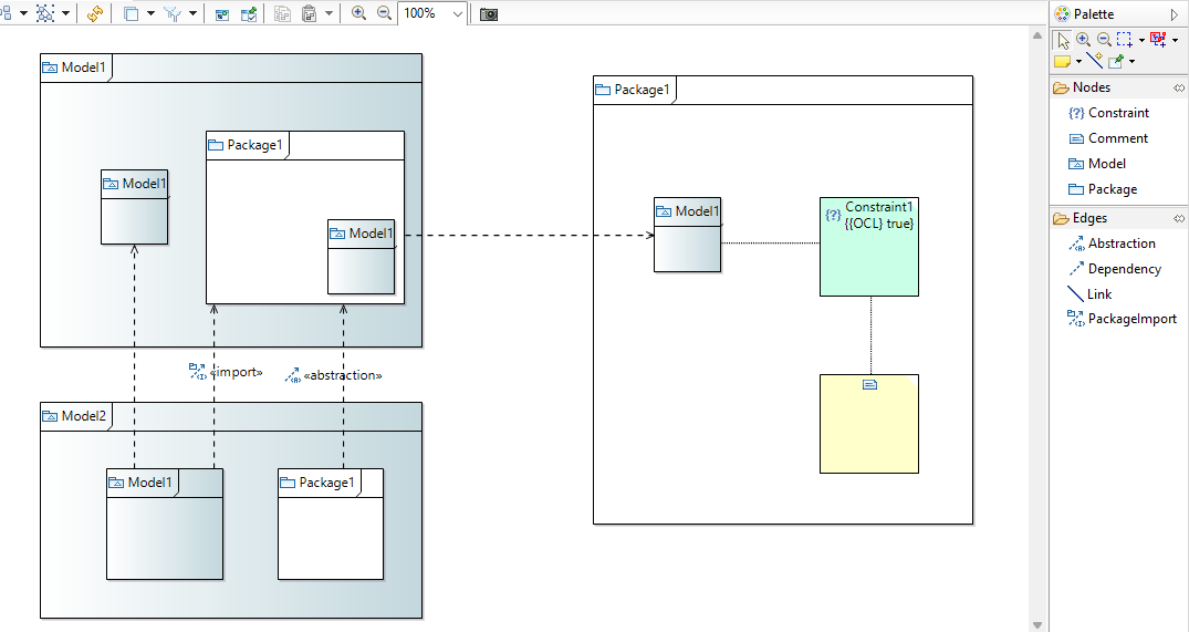
Same format as for the Composite Structure diagram is used here.
Here are some specific behavior about the Pin in the Sirius based ActivityDiagram:
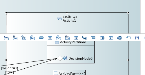
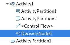
Some containers do not contain semantically their graphical nodes. This is the case for ActivityPartition and InterruptibleActivityRegion.
ActivityNodes contained in those containers are owned by the first parent Activity.
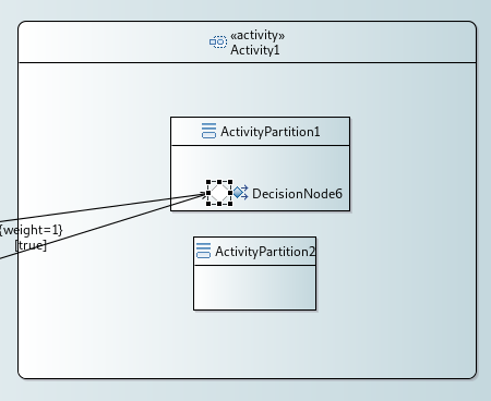
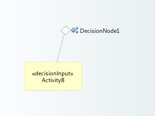
A note attached to the DecisionNode is displayed when the DecisionNode#decisionInput feature is set.
Note that when deleting the DecisionNode from the diagram, the note might still be present. Indeed, the delete from diagram action does not trigger the refresh of the diagram.
You need to manually perform the refresh to make the note disappear (F5 or the refresh tab-bar button).
Edges are allowed between Nodes with their type matching the correct type of source and target. If Edge is not authorized, a forbidden decorator will appear. It is not possible for now to create an edge between two Edges or between an Edge and a Node.
DirectEdit on this diagram only authorizes to edit the name of the element on which DirectEdit tool is activated. Remember that direct Edit can be launched with F2 key or double click on label.
Same rules as for the Composite Structure diagram are used here.
Same rules as for the Composite Structure diagram are used here. No specific cases have been implemented here.
Same rules as for the Composite Structure diagram are used here.
Same format as for the Composite Structure diagram is used here.
DirectEdit on this diagram only authorizes to edit the name of the element on which DirectEdit tool is activated. Remember that direct Edit can be launched with F2 key or double click on label.
No graphical drop is authorized on this diagram because there is no Container node.
Same rules as for the Composite Structure diagram are used here. Some specific cases have been implemented:
Same rules as for the Composite Structure diagram are used here.
Same format as for the Composite Structure diagram is used here.
DirectEdit on this diagram only authorizes to edit the name of the element on which DirectEdit tool is activated. Remember that direct Edit can be launched with F2 key or double click on label.
Same rules as for the Composite Structure diagram are used here.
Same rules as for the Composite Structure diagram are used here. Some specific cases have been implemented here:
Same rules as for the Composite Structure diagram are used here.
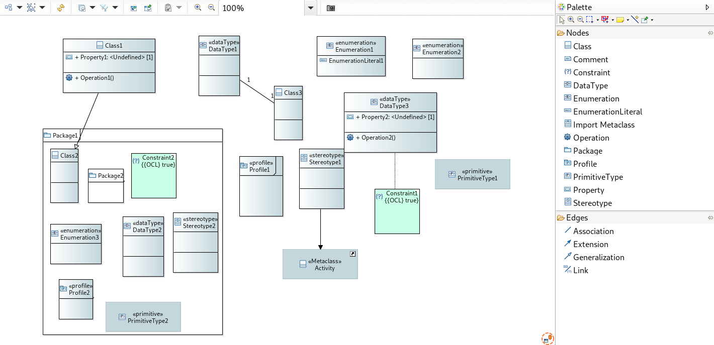
Keywords on Node and Edge are displayed in the first separate line of the label. If the semantic element is stereotyped, the stereotype is displayed in a second separate line (only when the stereotype layer is activated). Finally, the internationalized label will be displayed on the third line. The internationalized label displayed can be the qualified label if the corresponding layer is activated. It also can be the simple name of the element if there is no internationalized label and for specific case, the label can be more complex. For example, on Property, the label can contain Direction and name and type.
Each created NamedElement is automatically named. Strategy used to build the name of new element is the same than the third option in Papyrus preference naming strategy called "Unique index". The name convention forces a unique index by looking at all the contents of the current parent and looking for all elements that have the same name without the suffix (i.e. name of the Metaclass to create without any number). Finally the name of the new element is given by its Metaclass name suffixed by the number of element with the same name incremented by one.
Edges are allowed between Nodes with their type matching the correct type of source and target. If Edge is not authorized, a forbidden decorator will appear. It is not possible for now to create an edge between two Edges or between an Edge and a Node.
DirectEdit on this diagram only authorizes to edit the name of the element on which DirectEdit tool is activated. Remember that direct Edit can be launched with F2 key or double click on label.
If a user want to drag and drop a graphical element in another one, he has to select an element on the diagram and drag and drop it in a new element.
General rule for graphical drag and drop is the following one.
You can drag and drop an element in a new container where the drag and drop element type is accepted as a child of the new container. For example, you can drag and drop an Activity from its container into Classifier or Package.
Some specific cases have been implemented :
If a user want to drag and drop an element from the model explorer view on the diagram, he has to select the element from ModelExplorer view and drag and drop it into its container Node in the diagram (no semantic modification). Semantic drag and drop will always be authorized in its container representation except for specific case :
Semantic drag and drop of Edge will drag and drop Edge on diagram if it does not already exist. If source Edge or target Edge or both are not represented on diagram, source and/or target will be drag and drop too.
To reconnect an Edge, users can click on the source or target of the Edge to reconnect and drag and drop this end Edge on a new element. If the new source or target is an element represented with a compartment, the user can drag and drop the end Edge on the compartment of the element or on the header of the element, reconnection will work in both cases.
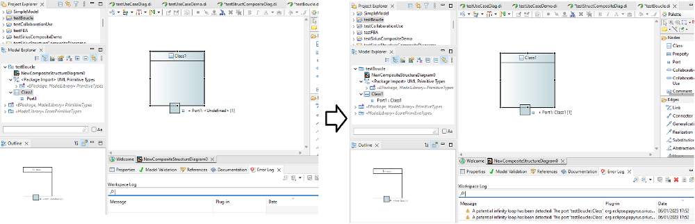
On a synchronized diagram, it is possible to create infinity representation loop on property typed with its container directly or indirectly. Indeed, on property typed in synchronized diagram, content of the type is represented in the property. So if a port is type by its container, the port is represented on the port and so on.
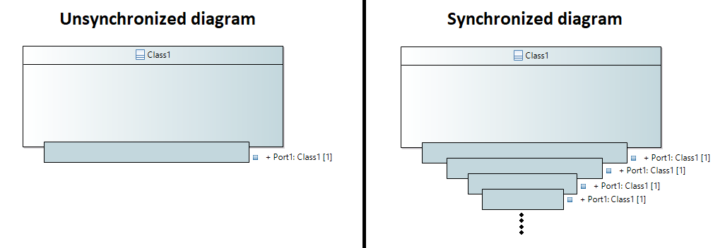
To avoid this configuration, every Node detected in the infinity loop will not be represented and an error message will be display in the Error Log.
This message warn user that "A potential infinity loop has been detected: The port XXX is typed by XXX which directly or indirectly references XXX through ports type hierarchy."
Same format as for the Composite Structure diagram is used here.
DirectEdit on this diagram only authorizes to edit the name of the element on which DirectEdit tool is activated. Remember that direct Edit can be launched with F2 key or double click on label.
Same rules as for the Composite Structure diagram are used here.
Same rules as for the Composite Structure diagram are used here. No specific cases have been implemented here.
Same rules as for the Composite Structure diagram are used here.
Same format as for the Composite Structure diagram is used here.
DirectEdit on this diagram only authorizes to edit the name of the element on which DirectEdit tool is activated. Remember that direct Edit can be launched with F2 key or double click on label.
No graphical drop is authorized on this diagram because there is no Container node.
Same rules as for the Composite Structure diagram are used here. No specific cases have been implemented here.
Same rules as for the Composite Structure diagram are used here.
Same format as for the Composite Structure diagram is used here.
Edges are allowed between Nodes with their type matching the correct type of source and target. If Edge is not authorized, a forbidden decorator will appear. It is not possible for now to create an edge between two Edges or between an Edge and a Node.
DirectEdit on this diagram only authorizes to edit the name of the element on which DirectEdit tool is activated. Remember that direct Edit can be launched with F2 key or double click on label. It is not possible to activate the direct edit on an imported metaclass.
Same rules as for the Composite Structure diagram are used here. No specific cases have been implemented here.
Same rules as for the Composite Structure diagram are used here. No specific cases have been implemented here.
Same rules as for the Composite Structure diagram are used here. When reconnecting an Extension target to another Class, the Stereotype property type is updated.
Same format as for the Composite Structure diagram is used here.
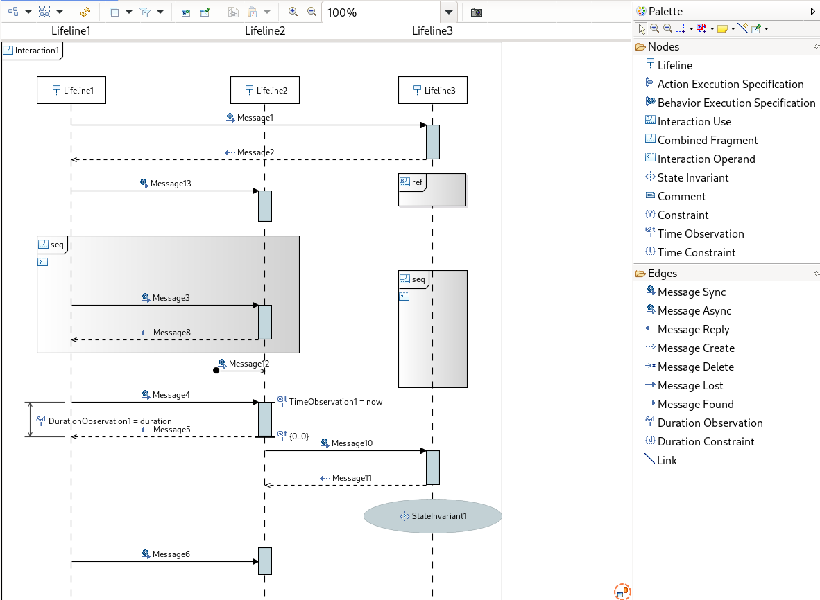
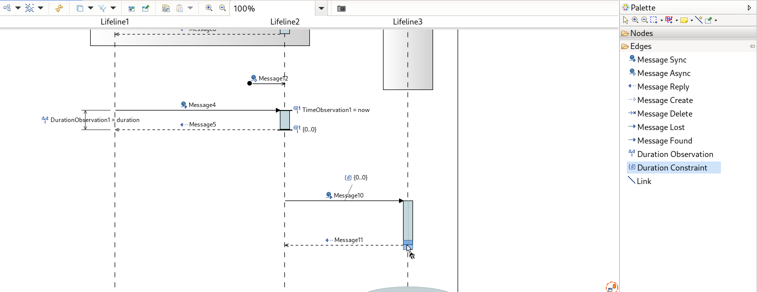
We describe here some specific features. For other features, see the sections below for more details.
It is highly recommended to avoid direct model modifications (adding or removing elements) out of the Sequence Diagram (by using the Model Explorer for instance).
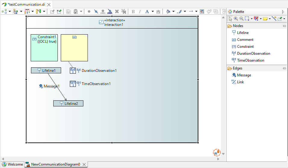
In the sequence diagram, messages are allow between lifeline and executions. Messages can be recursive on the same execution or lifeline.
DirectEdit on this diagram only authorizes to edit the name of the element on which DirectEdit tool is activated. Remember that direct Edit can be launched with F2 key or double click on label.
Note: An execution with at least one message connected cannot be moved. With this restriction, we avoid complex reordering issues.
The Sequence diagram allows to drop a Property or a Class from the semantic explorer on the diagram.
lifeline#represents feature is set with the dropped property.lifeline#represents feature is set with the created property.lifeline#represents feature is set as described above.
Same format as for the Composite Structure diagram is used here.
Edges are allowed between Nodes with their type matching the correct type of source and target. If Edge is not authorized, a forbidden decorator will appear. It is not possible for now to create an edge between two Edges or between an Edge and a Node.
DirectEdit on this diagram only authorizes to edit the name of the element on which DirectEdit tool is activated. Remember that direct Edit can be launched with F2 key or double click on label.
Same rules as for the Composite Structure diagram are used here.
Some specific cases have been implemented :
Same rules as for the Composite Structure diagram are used here. No specific cases have been implemented here.
Same rules as for the Composite Structure diagram are used here.